With a CompactLogix

controller
• For expansion I/O in a MicroLogix
1500 controller assembly
• In an assembly with a 1769-ADN DeviceNet adapter
• In an assembly with a 1769-AENTR Ethernet adapter.
Unless connected to a MicroLogix 1500 base, each bank of I/O modules must include its own power supply.
Install the I/O modules on a panel with two mounting screws or on a DIN rail. The modules mechanically lock together
with a tongue-and-groove design and have an integrated communication bus that is connected from module to module by
a moveable bus connector
• Once the modules are locked together, the system becomes a rugged assembly.
• Upper and lower tongue-and-groove slots guide the module during installation and secure the module within thesystem.
• Removable terminal blocks help ease the wiring task.
• Self-lifting, field-wire pressure plates cut installation time.
• The patented bus connector with the lock function enables consistent and system communication.
• A color bar is provided on the front of the module.
• Digital and field circuits are optically isolated.
Digital I/O Modules
Choose digital I/O modules when you need these features.
Most output modules have built-in surge suppression to reduce the effects of high-voltage transients. Use an additional suppression device if an output is being used to control inductive devices, such as relays, motor starters, solenoids, ormotors.
Type Description
Input An input module responds to an input signal in the following manner:
• Input filtering limits the effect of voltage transients that contact bounce and/or electrical noise cause. If not filtered, voltage transients could produce false data. All input modules use input filtering.
• Optical isolation shields logic circuits from possible damage due to electrical transients.
• Logic circuits process the signal.
• An input indicator turns on or off, which indicates the status of the corresponding input device.
Output An output module controls the output signal in the following manner:
• Logic circuits determine the output status.
• An output indicator displays the status of the output signal.
• Optical isolation separates module logic and bus circuits from field power.
Similar Products
140AII33010 140DII33000C 140CRA21210C 140DDO88500C 140XCP90000
140AII33010C 140NOE77101 140EIA92100C 140DRA84000C 140XBE10000
140CHS41020 140NOM21200C 140CPS21400C 140DDO35300 140XCP90000C
140CHS41010 140ACO13000 140CPS22400 140DAM59000C 140XBP00400C
140CPU67160S 140ESI06210C 140CPS52400 140DDM69000 140XBP00300C
140CPU65260C 140ARI03010C 140CPS12420C 140DDM39000C 140CFB03200
140CPU67160C 140ATI03000C 140CRA21220C 140DDI84100C 140CFE03200
140CPU65160C 140CRP93200 140SDI95300S 140DAI34000C 140XBP00600
140CHS21000C 140CRA93200 140DSI35300C 140DAI44000C 140CFD03200
140CPU67160 140DII33000 140CRA21210 140DAO84210C 140XBP00200C
140CHS21000 140NOM21200 140CPS12420 140DAO84220C 140CPS51100
140CPU65260 140DVO85300C 140CRA21120C 140DDI67300 140XBE10000C
140CPU53414BC 140ARI03010 140CPS21400 140DDI35310 140SHS94500
140CPU65160S 140ATI03000 140DAO85300C 140DAI54000C 140DAI54300
140CPU65160 140ESI06210 140CRA21110C 140DAI74000C 140XBP00600C
140CPU53414B 140ERT85410 140CRA21220 140DDI15310 140XBP01000
Main
range of product
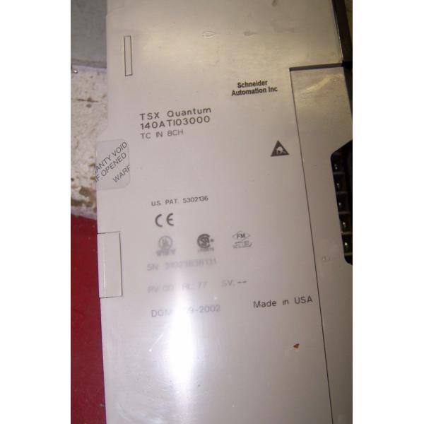
Modicon Quantum automation platform
product or component type
Analogue input module
type of filter
Notch filter - 3 dB at 50/60 Hz
Single pole low pass - 3 dB at 20 Hz
Complementary
analogue input number
8
addressing requirement
10 input words
analogue input type
Thermocouple: - 210...760 °C for thermocouple J
Thermocouple: - 270...1000 °C for thermocouple E
Thermocouple: - 270...1370 °C for thermocouple K
Thermocouple: - 270...400 °C for thermocouple T
Thermocouple: - 50...1665 °C for thermocouple R
Thermocouple: - 50...1665 °C for thermocouple S
analogue input resolution
16 bits
input impedance
> 1 MOhm
absolute accuracy error
+/- 2 °C plus + 0.1 % of reading thermocouple E
+/- 2 °C plus + 0.1 % of reading thermocouple J
+/- 2 °C plus + 0.1 % of reading thermocouple K
+/- 2 °C plus + 0.1 % of reading thermocouple T
+/- 4 °C plus + 0.1 % of reading thermocouple R
+/- 4 °C plus + 0.1 % of reading thermocouple S
linearity error
1 °C, 0.1 °C, 1 F, 0.1 F - 210...760 °C
1 °C, 0.1 °C, 1 F, 0.1 F - 270...1000 °C
1 °C, 0.1 °C, 1 F, 0.1 F - 270...1370 °C
1 °C, 0.1 °C, 1 F, 0.1 F - 270...400 °C
1 °C, 0.1 °C, 1 F, 0.1 F - 50...1665 °C
accuracy drift according to temperature
0.15 µV/°C + 0.0015 % of reading/°C max low level voltage
common mode rejection
> - 120 dB 50/60 Hz
isolation between channels and bus
1780 V AC for 60 s
2500 V DC for 60 s
isolation between channels
300 V DC
220 V AC
update time
1000 ms
fault type
Broken wire
Overtacking scale
marking
CE
cold junction compensation
Internal 0…60 °C
local signalling
1 LED (green)bus communication is present (Active):
1 LED (red)external fault:
8 LEDs (green)channel is turned on:
8 LEDs (red)channel fault: